Aplanatic secondary concentrators for solar towers
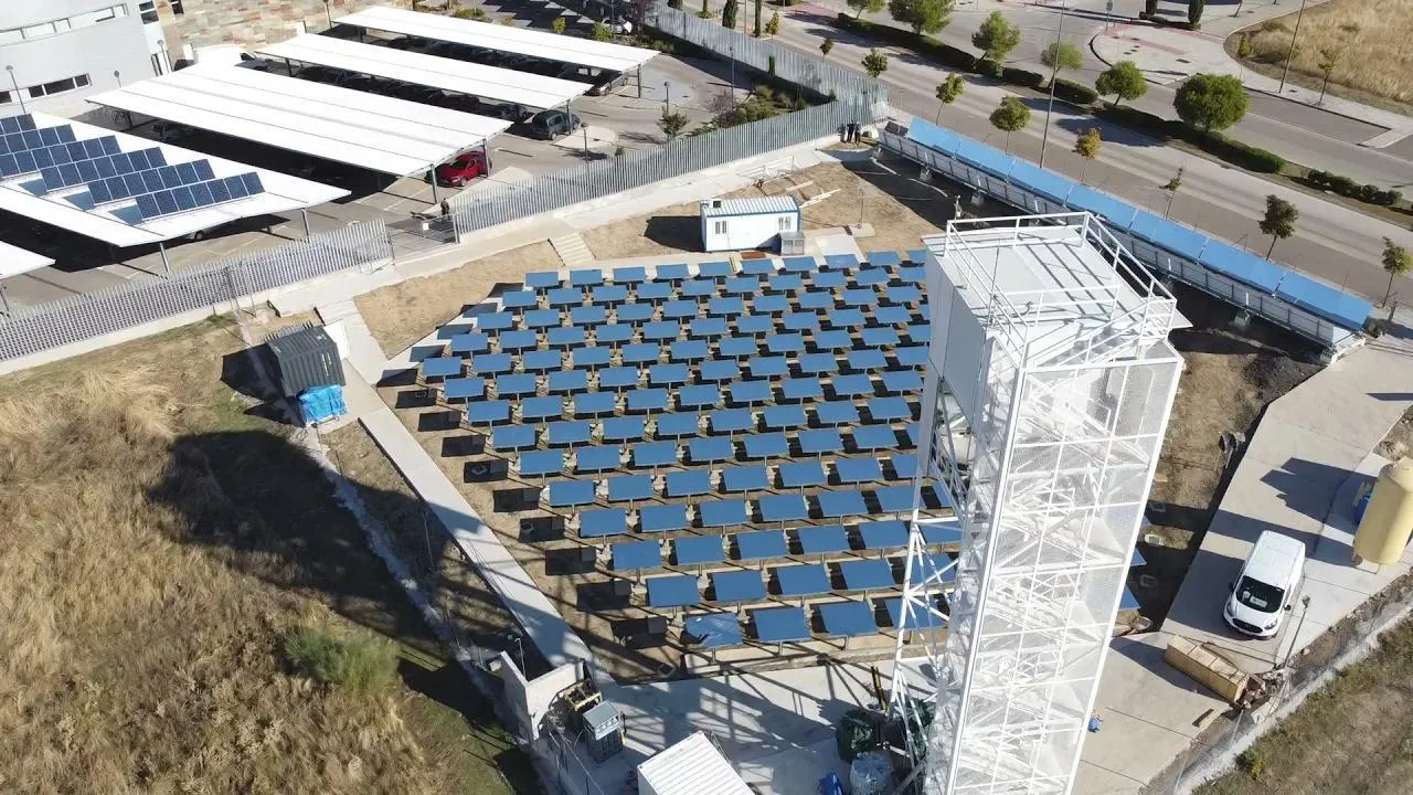
Image Credit: IMDEA Energy
In October 2024, I gave a presentation at the SolarPACES conference on an interesting type of secondary concentrator for high-temperature solar thermal applications.
This post is an overview and explanation of the slides from that presentation. You can also download the original PDF with the slides.
One way to use solar energy is to concentrate it, convert it to high-temperature heat, and then use this heat to drive a chemical reaction or generate electricity. This is known as concentrated solar power (CSP). There are good, established designs for reaching the very high concentrations needed for thermochemical applications, and there are good, established designs for scaling solar concentrators to hundreds of megawatts. The problem is that these are different designs, so there is a tradeoff between scalability and concentration.
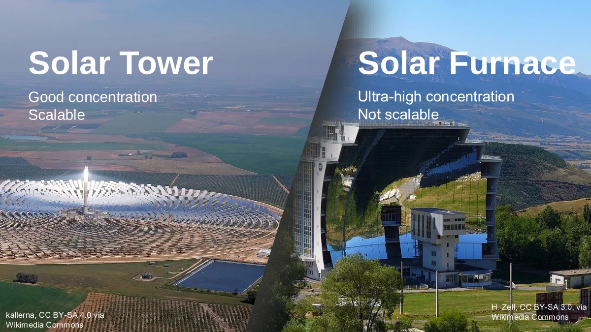
On the left is a solar tower. Many mirrors, each tracking the sun, send light to a target on the tower. This concept is inherently scalable, with fields existing in many different sizes, from very small research fields to huge fields for electricity production.
On the right is a solar furnace. A furnace is usually built around a large parabolic mirror, with one or more heliostats sending light into it. This optical configuration has way higher concentration, making this type of configuration useful for high-temperature testing, material science, and solar thermochemistry. However it is not very scalable. The picture shows the Odeillo solar furnace in France, which is the largest solar furnace in the world and as you can see it consists of a whole multi-story building where one of the walls is a huge parabolic mirror.
This is the tradeoff: we need to choose between the high concentration of solar furnaces and the high scalability of solar towers.
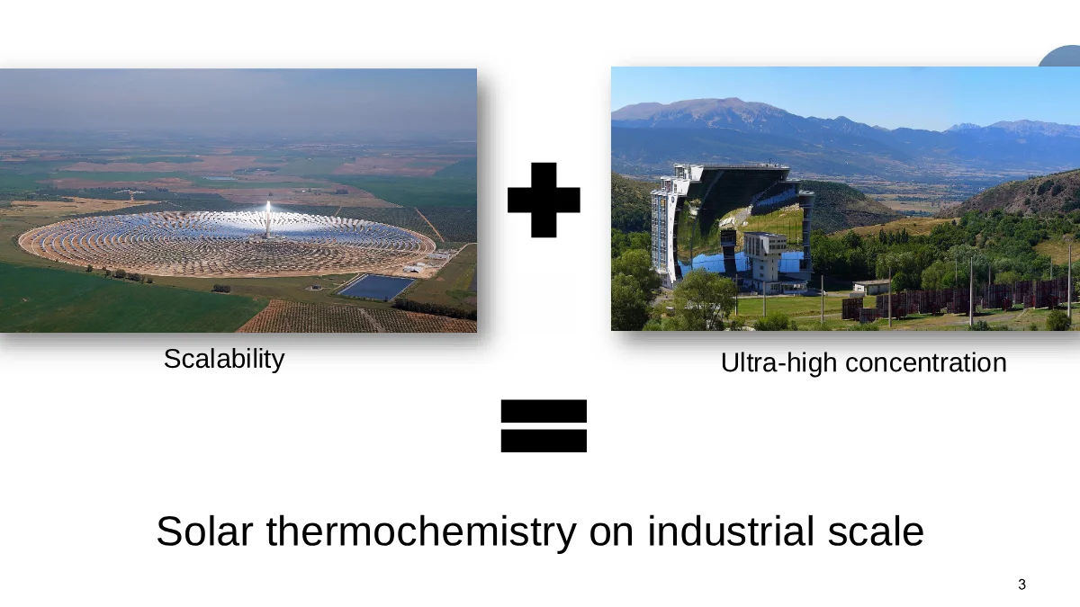
What if we could combine the two and develop a design that provides the concentration of a solar furnace at the scale of a solar tower? This would enable us to take research ideas such as high-temperature industrial solar thermochemistry, which requires very strong concentration, and implement them at an industrial scale.
Our goal is to achieve this combination:
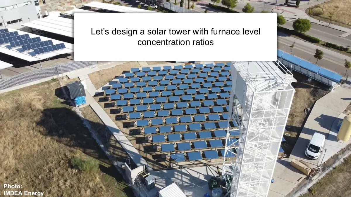
To demonstrate our approach, we will look at a specific solar tower, the IMDEA Energy solar tower in Madrid. This is a small research field which is already used for solar thermochemistry, and we will see if it is possible to push this field towards the concentration levels of a solar furnace.
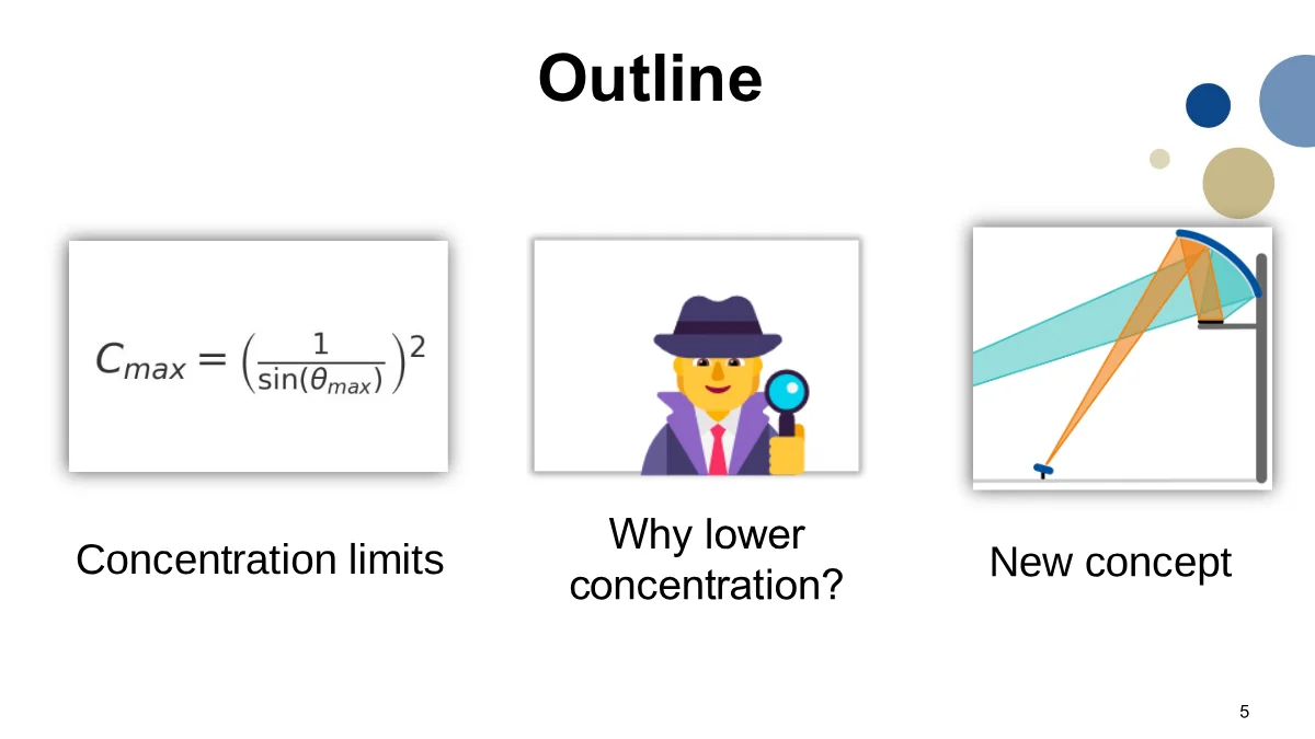
To do this, we will need to explore what the actual limits of concentration are for solar towers, why conventional heliostat fields do not reach those limits, and that will lead us to a new concept for getting higher concentration in solar towers.
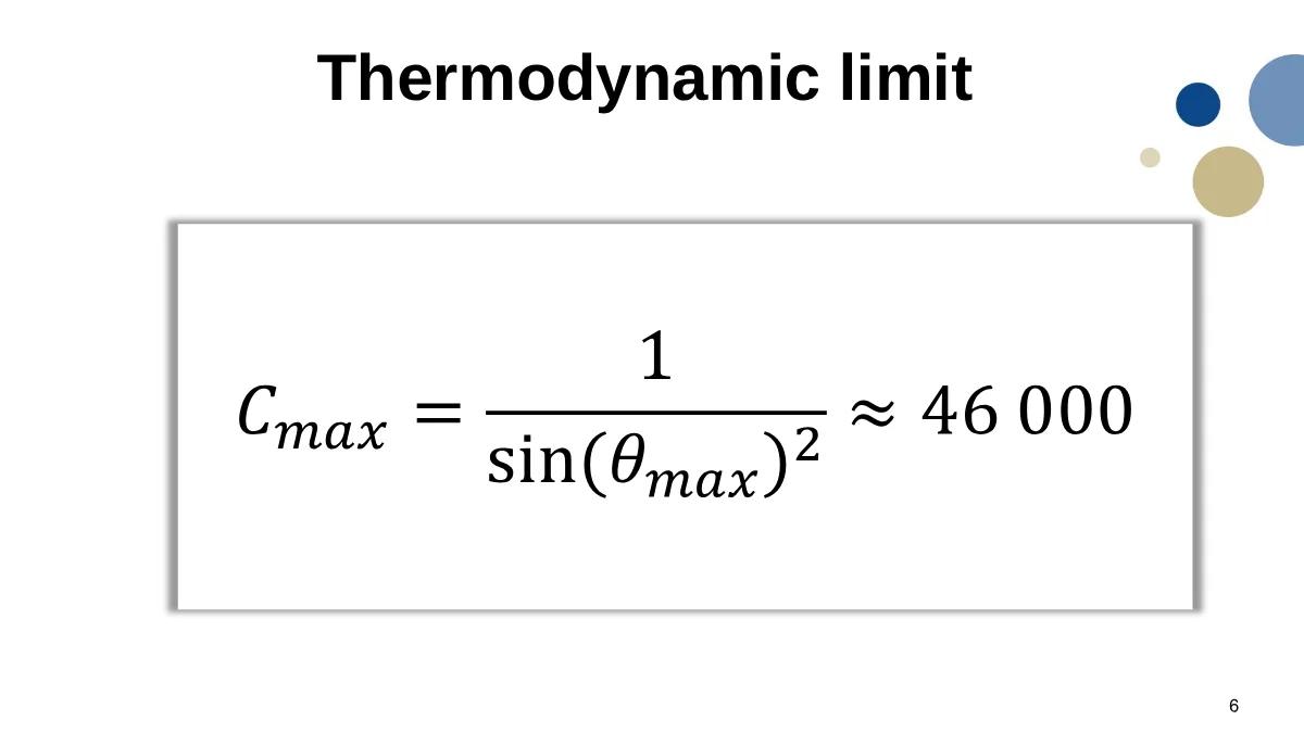
The maximum concentration for a solar concentrator is well known. In air, it is approximately 46,000 suns, or about 41 MW/m².
That is a very high number. So an ideal concentrator can, at least in principle, concentrate sunlight extremely strongly.
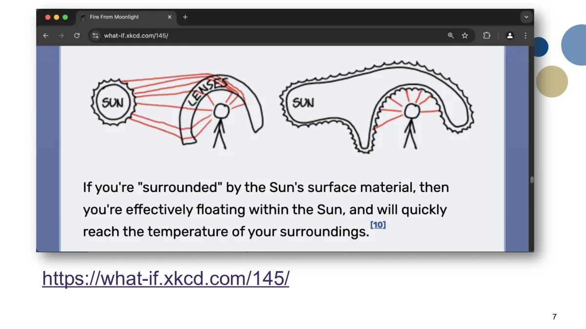
In fact, this limit is closely related to the second law of thermodynamics. The maximum temperature that you can obtain from a source is the temperature of the source itself. This occurs when the optics make it look as though you are completely surrounded by the source, as nicely illustrated by Randall Munroe in a What If? post:
With that in mind, we can look at the Very-High Concentration Solar Tower at IMDEA Energy in Madrid:
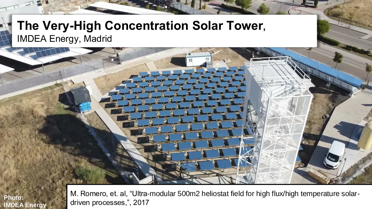
This field was built to get as high a concentration as possible. The design is documented in Romero et al.’s 2017 paper “Ultra-modular 500 m² heliostat field for high flux/high temperature solar-driven processes”.
Let’s take the concentrated spot of sunlight from this field and compare it with a simulated spot from a thermodynamically ideal solar field:
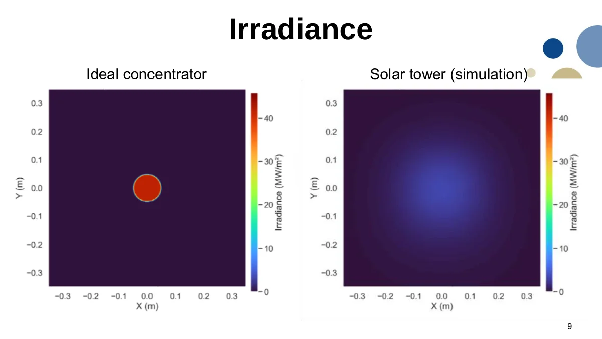
The IMDEA Energy field’s spot is so much weaker that it almost does not show up in our comparison plot.
If we turn down the scale on the solar-tower plot, we can see that there is concentrated sunlight there. But the spot is much more smeared out, and the peak flux density is lower by more than a factor of ten:
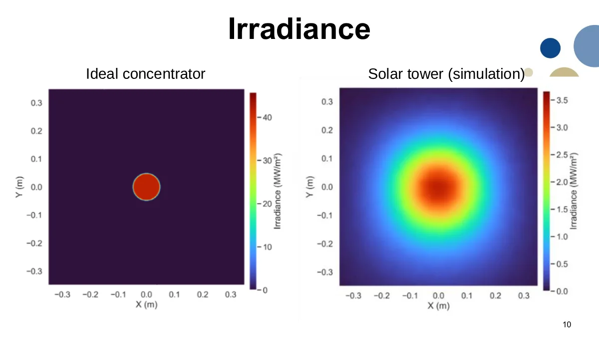
So the question is: why is there such a huge discrepancy between the ideal concentrator and the heliostat field?
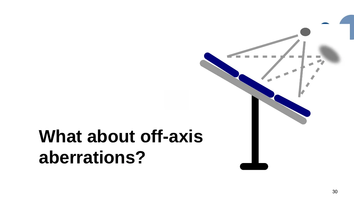
The first explanation that comes to mind if you ask people in this field is heliostat quality. Real heliostats are physical systems with errors and inaccuracies, including tracking errors, canting errors, mirror-shape errors, and off-axis aberrations from the individual heliostats.
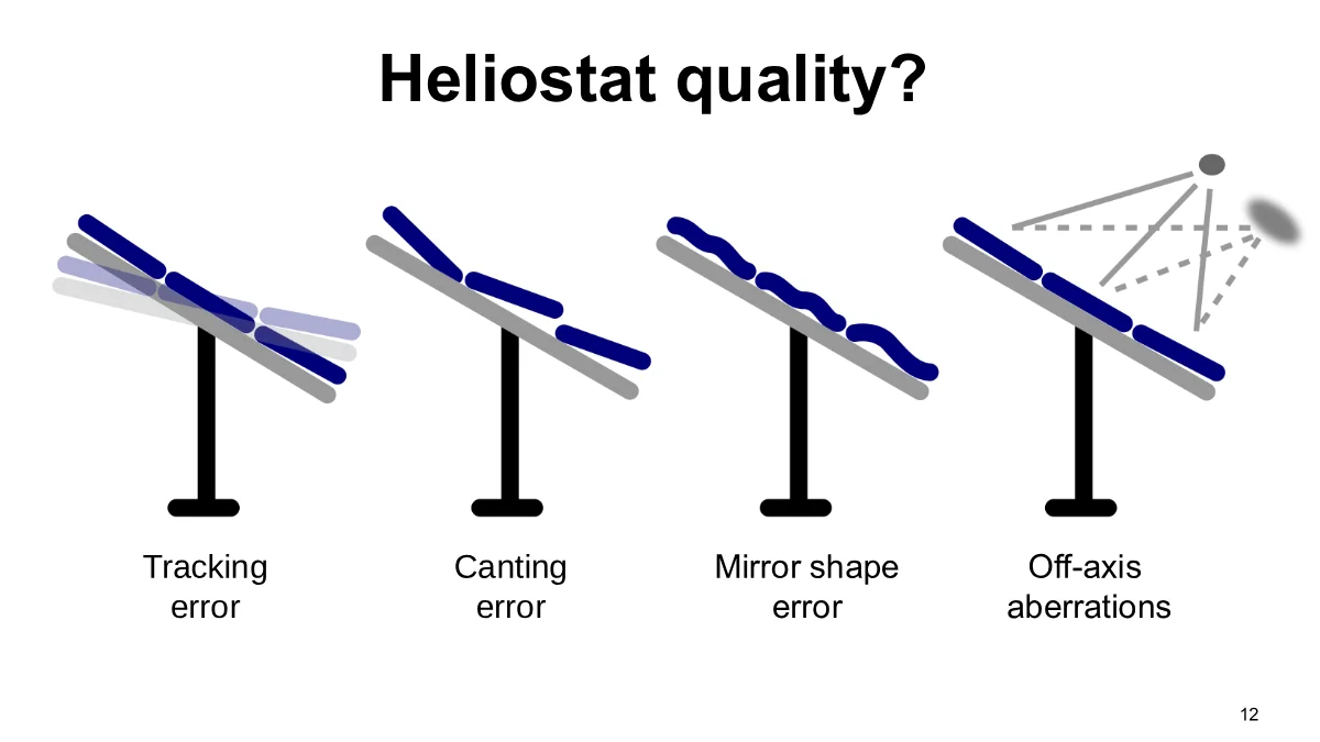
Each small error in the surface normal of a heliostat mirror sends the light to a slightly incorrect point and contributes to the blur of the concentrated sunlight. Improving heliostat quality certainly improves the concentration of the light. But is it enough?
Let’s simulate the IMDEA Energy field again, this time eliminating all errors and assuming that the heliostats are perfect:
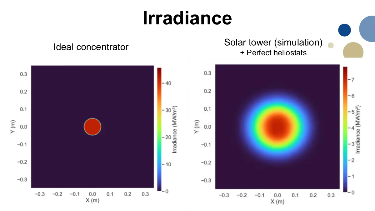
The result is better, but it is still very far from ideal. The spot is clearly very blurry and is still only about one-sixth as intense as the prediction for a thermodynamically ideal concentrator.
This means heliostat quality matters, but it is not the whole story.
The next suspect is the numerical aperture. In an ideal concentrator, sunlight comes from the whole hemisphere above the receiver, which we call a numerical aperture of 1. In a heliostat field, sunlight comes from a much smaller set of angles:
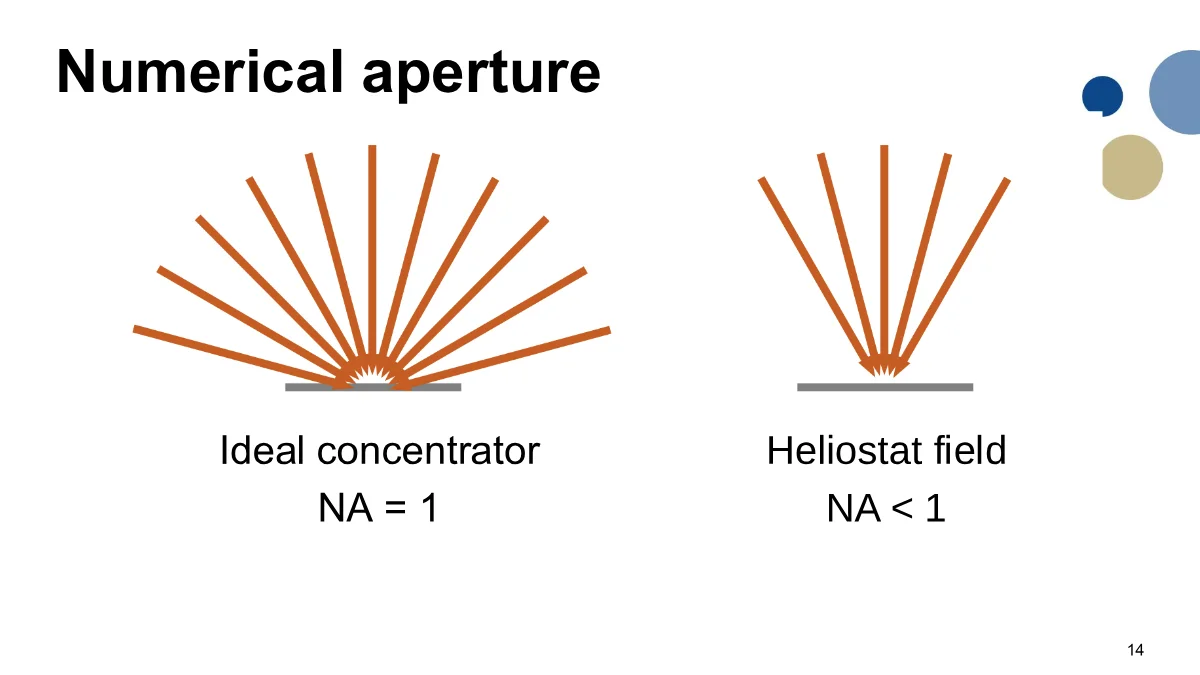
We know how to increase the numerical aperture. The classical approach is to use a secondary concentrator, such as a compound parabolic concentrator, to boost the numerical aperture toward 1. Let’s simulate this approach and the concentration boost we would obtain by increasing the numerical aperture to 1:
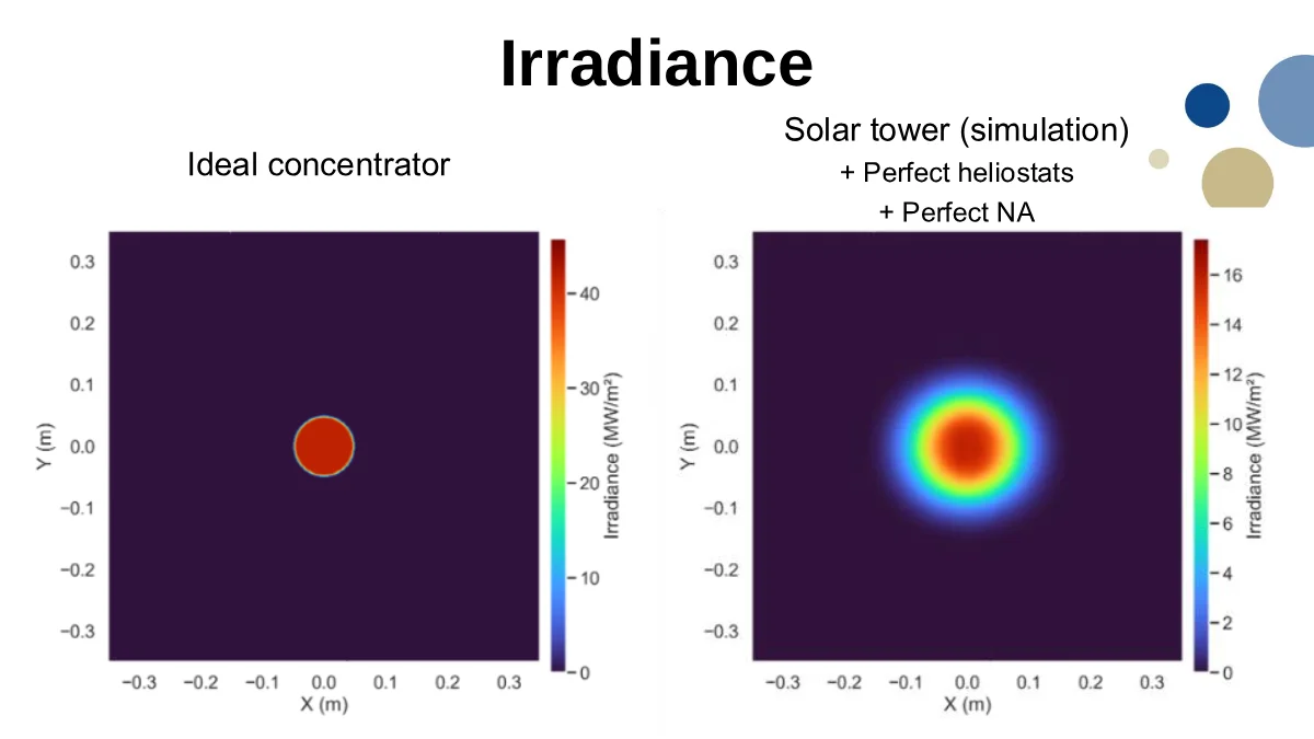
This helps a lot. The peak is around 16 MW/m². But it is still lower than the ideal case, and the spot is still smeared out.
Why?

Now we have tried the two obvious explanations. We made the heliostats perfect, and we gave the system a perfect numerical aperture, but we still did not get the ideal concentration. This is where optimization of high-concentration heliostat fields usually stops.
But I think we should take it one step further:
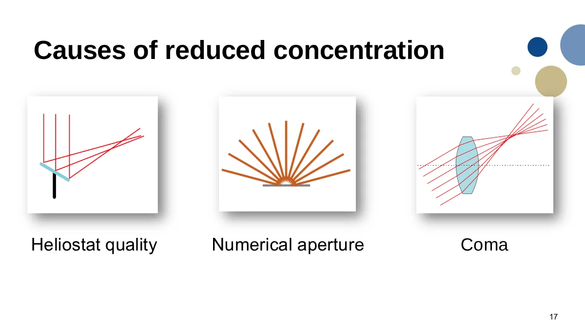
It turns out, perhaps somewhat surprisingly, that the third factor we were missing is coma:
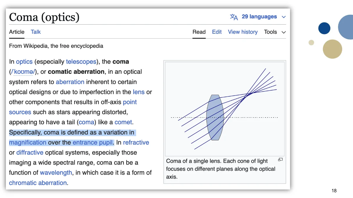
Coma, or comatic aberration, is a variation in magnification over the entrance pupil of an optical system.
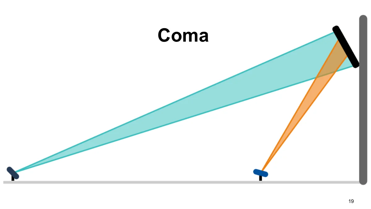
In the heliostat field, coma appears in the way each heliostat is designed to create an image of the sun on the receiver. The farther away a heliostat is, the larger this image becomes because the light must travel farther before reaching the target. If we consider the entire heliostat field as one optical system, this is equivalent to coma.
This is actually good news because we know how to correct coma. What we need is an optical design known as aplanatic optics. In solar concentration, this approach has been strongly advanced by Jeffrey Gordon and co-authors. The basic message is that aplanatic optics can get very close to the thermodynamic limit of optical concentration:
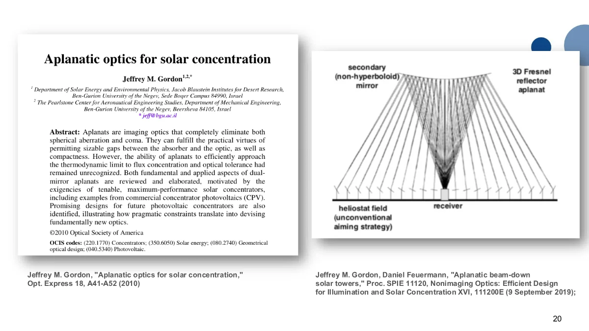
Gordon even proposed applying this idea to heliostat fields in the form of an aplanatic beam-down tower. This initially sounds difficult because correcting coma typically requires two free surfaces, and we have only one secondary-concentrator surface. However, Gordon realized that if the heliostat field consists of many small heliostats, we can use their aimpoints as a degree of freedom for correcting coma.
So one degree of freedom is the freeform secondary, and another is where each heliostat points. Together, those are enough to design an aplanatic system.
After I presented this talk, I also learned that the basic idea was independently explored by Thomas Cooper and Roger Angel around the same time.
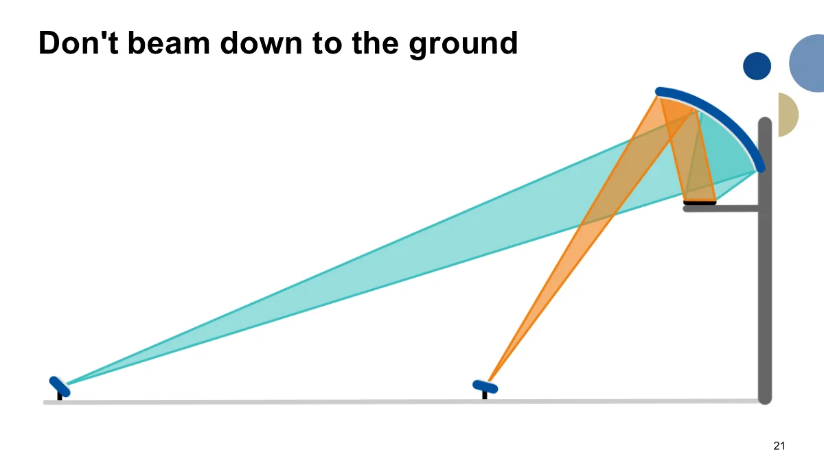
The beam-down idea is attractive in some ways, but it also has significant drawbacks. The secondary becomes very large, and it has to be supported and cleaned high up in the tower.
So the concept we are exploring is this: let’s not beam down to the ground. We keep the principle of using a secondary mirror together with an unconventional aiming strategy, but use it near the receiver instead.
If we can build this kind of secondary, it can work on two of the three problems at the same time:
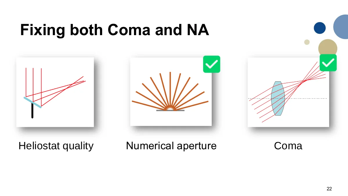
It can fix the numerical aperture because the secondary can send rays into the target from a much larger set of angles. It can also correct much of the coma because the secondary shape and the heliostat aiming strategy are designed together.
It does not fix heliostat quality. That is still a separate knob that we can tune to boost the concentration ratio even further.
There is one problem, though. For off-axis systems such as the IMDEA Energy heliostat field, the system is not completely solvable with only these two degrees of freedom:
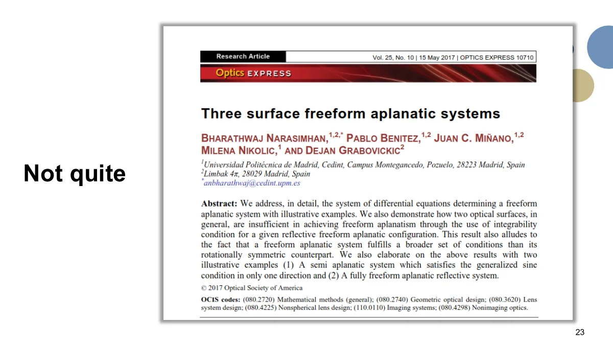
So we cannot make a perfect aplanatic system. But we can still take the two degrees of freedom we do have, optimize them, and see how far we get:
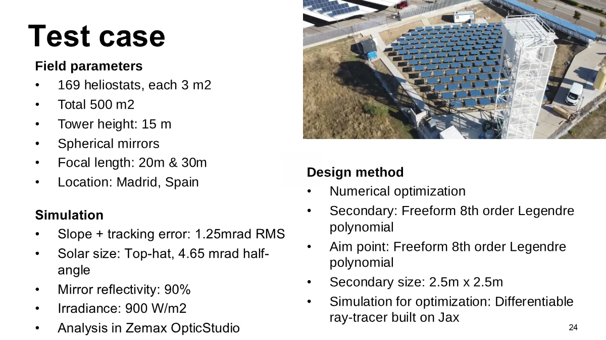
The simulation uses the slope and tracking errors reported in the paper on the field design so that the results are comparable.
For the design itself, both the secondary and the aiming strategy are optimized. Both are represented as 8th-order Legendre polynomials, and the optimization uses a differentiable ray tracer built on JAX.
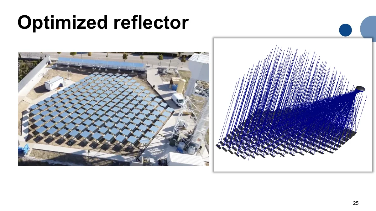
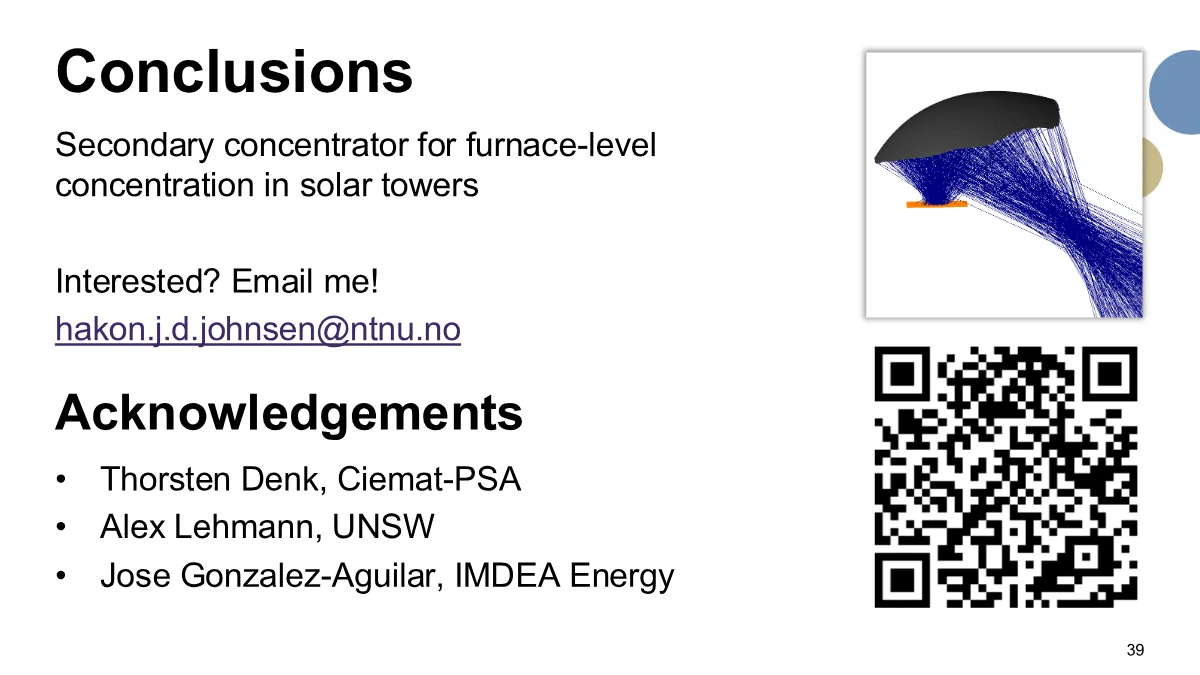
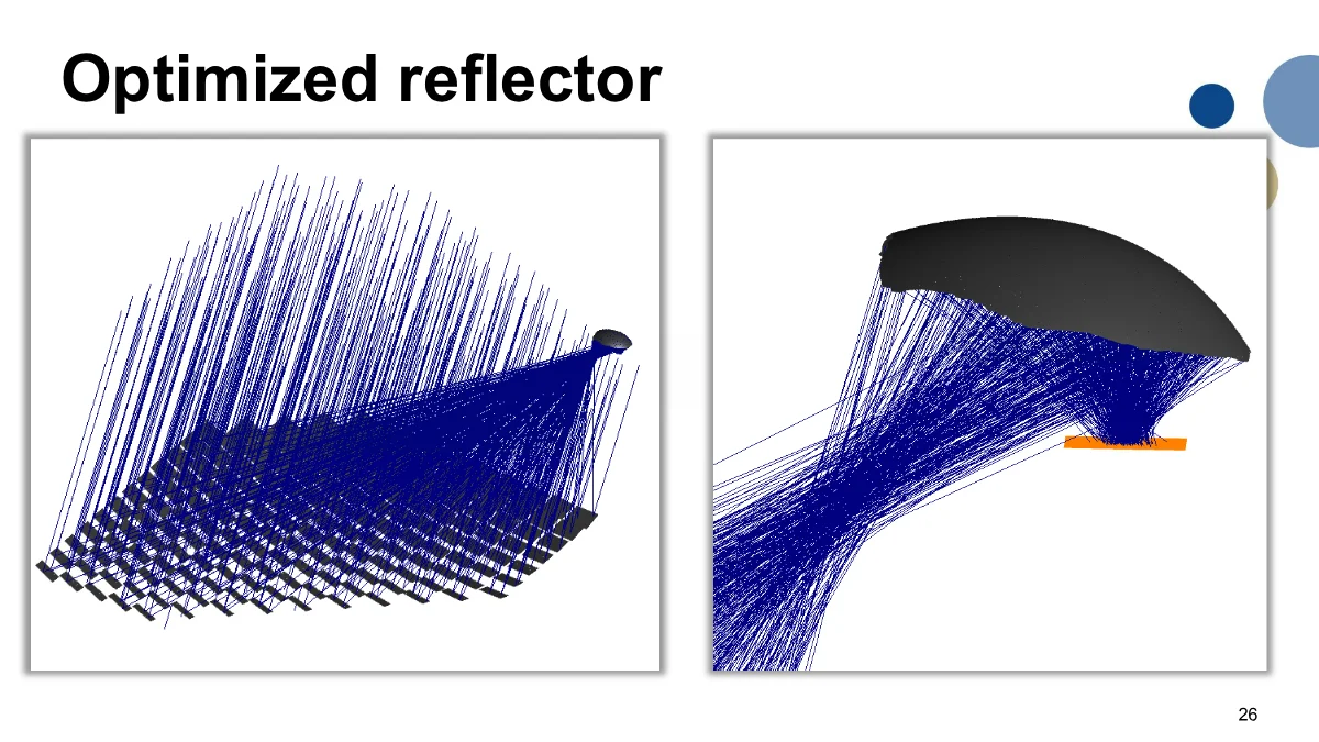
Here is the optimized reflector. The full heliostat field is on the left, and the secondary is up near the receiver.
The heliostats are not all aimed at the same point. They are aimed so that, together with the secondary surface, the bundle is reshaped before it hits the target.
The sunlight comes from the heliostat field, reflects from the secondary, and then hits a horizontal target:
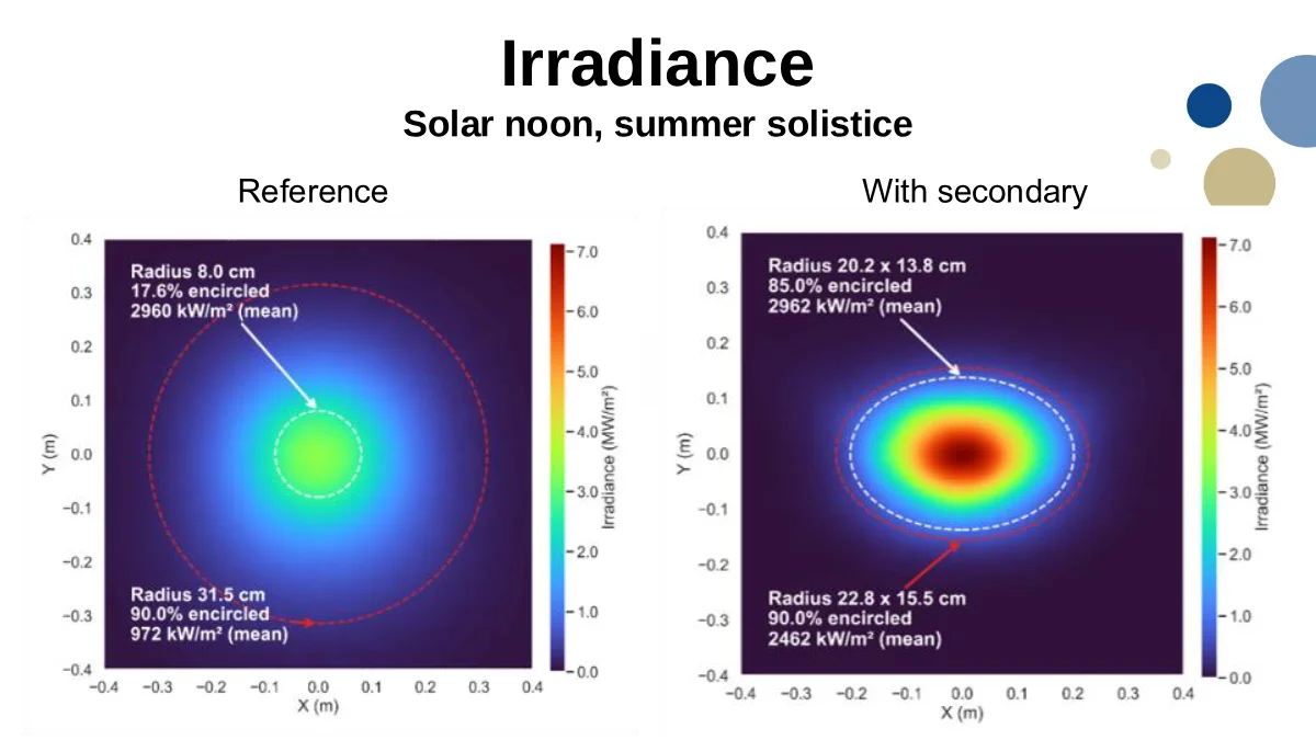
Here is the simulated irradiance distribution at solar noon on the summer solstice:
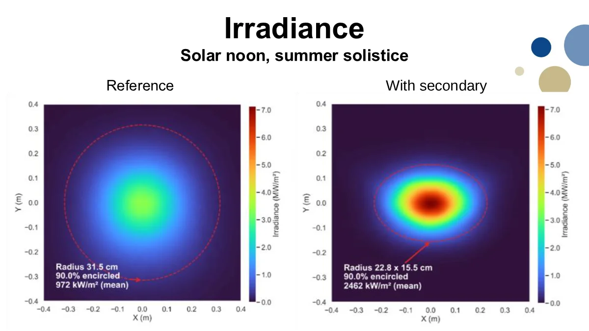
On the left is the reference case, which is what the field gives today on a flat target. On the right is the case with the secondary. The spot is smaller, and the average irradiance inside the 90% encircled-energy region increases from about 970 kW/m² to about 2500 kW/m².
The field was originally built for high-temperature thermochemical processes, and those processes require a very high average irradiance.
In the reference case, we must use a small aperture, take the central high-irradiance part, and throw away most of the rest as spillage. With the secondary, a much larger fraction of the sunlight achieves the concentration levels required to drive high-temperature thermochemical applications:
This meant that in the original heliostat-field design, approximately 80% of the power was wasted because the concentration was insufficient. We can use the secondary concentrator to significantly reduce this loss:
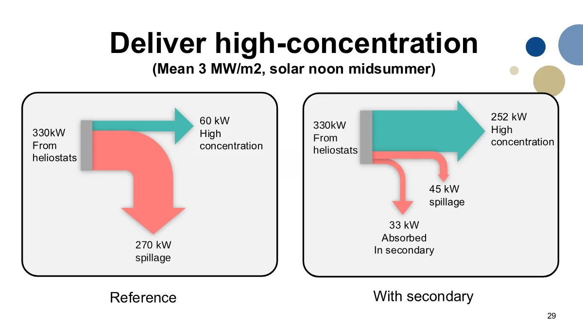
In the reference case, about 60 kW is delivered at the high concentration level, and about 270 kW becomes spillage. With the secondary, about 252 kW reaches the high-concentration region. There is still about 45 kW of spillage, and about 33 kW is absorbed in the secondary.
So for the original purpose of this field, the secondary gives much more useful power, not just a sharper spot.
The above results were simulated at the ideal time of the year: Solar noon in midsummer. The obvious next question then, is whether the proposed secondary only works for this ideal case, or whether it also works in the rest of the year.
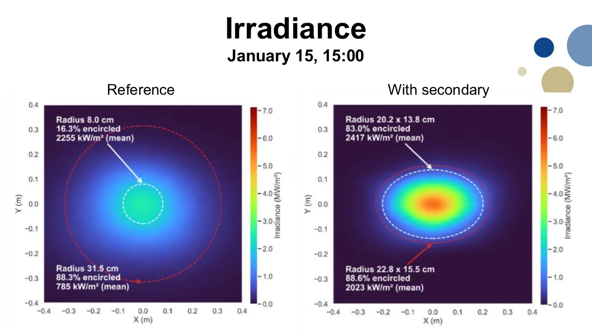
Above is simulated performance on January 15 at 15:00. Here the sun is low and away from the nice midsummer-noon geometry, so the overall irradiance is lower.
But the basic picture is still the same. The secondary gives a much more concentrated distribution than the reference. The reason this works is that the optimization uses the real heliostat geometry and optimizes the secondary concentrator for whole-year performance.
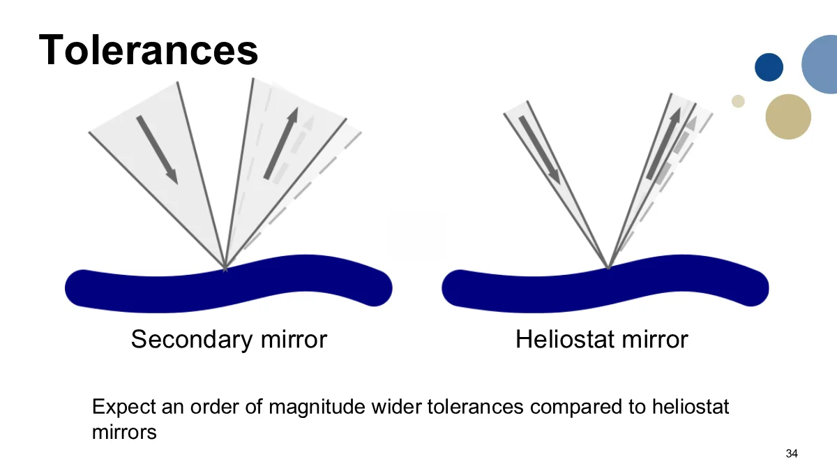
Another practical question is how difficult this will be to fabricate. What levels of tolerance will be acceptable for this secondary concentrator, and will its optical-quality requirements be as demanding as those for the heliostat field?
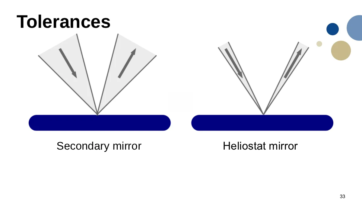
The short answer is no. The light is much more concentrated when it reaches the secondary mirror, which means that it contains a much broader set of angles. When the mirror has some slope error, the relative effect of that slope error is therefore much lower:
Cooling is the next obvious issue.
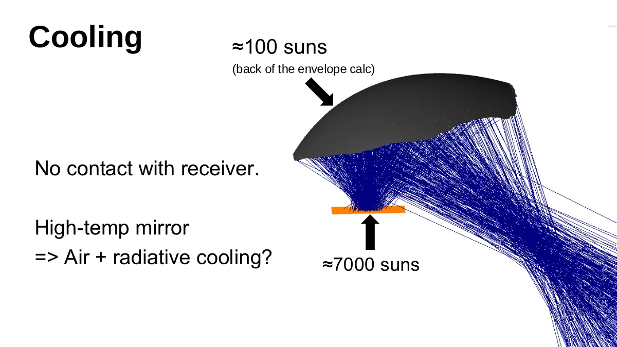
The good thing is that the secondary is not in contact with the receiver. It is larger than a classical CPC-type secondary, so cooling will be easier. It is still a high-temperature mirror and will still require cooling, but back-of-the-envelope calculations indicate that the cooling requirements will be an order of magnitude milder than for conventional CPC-like secondary concentrators for heliostat fields.
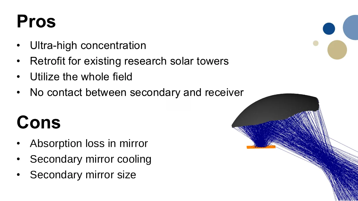
Advantages of this proposed approach are the high concentration, the possibility of retrofitting existing research solar towers, and the fact that we can use much more of the heliostat field for high concentration instead of throwing away most of the power as spillage.
Additionally, there is no contact between the secondary and the receiver which might make it easier to implement in practice than competing CPC-like secondary concentrators.
There are also disadvantages. There is absorption loss in the secondary mirror, the secondary needs cooling, and the secondary mirror is physically large.
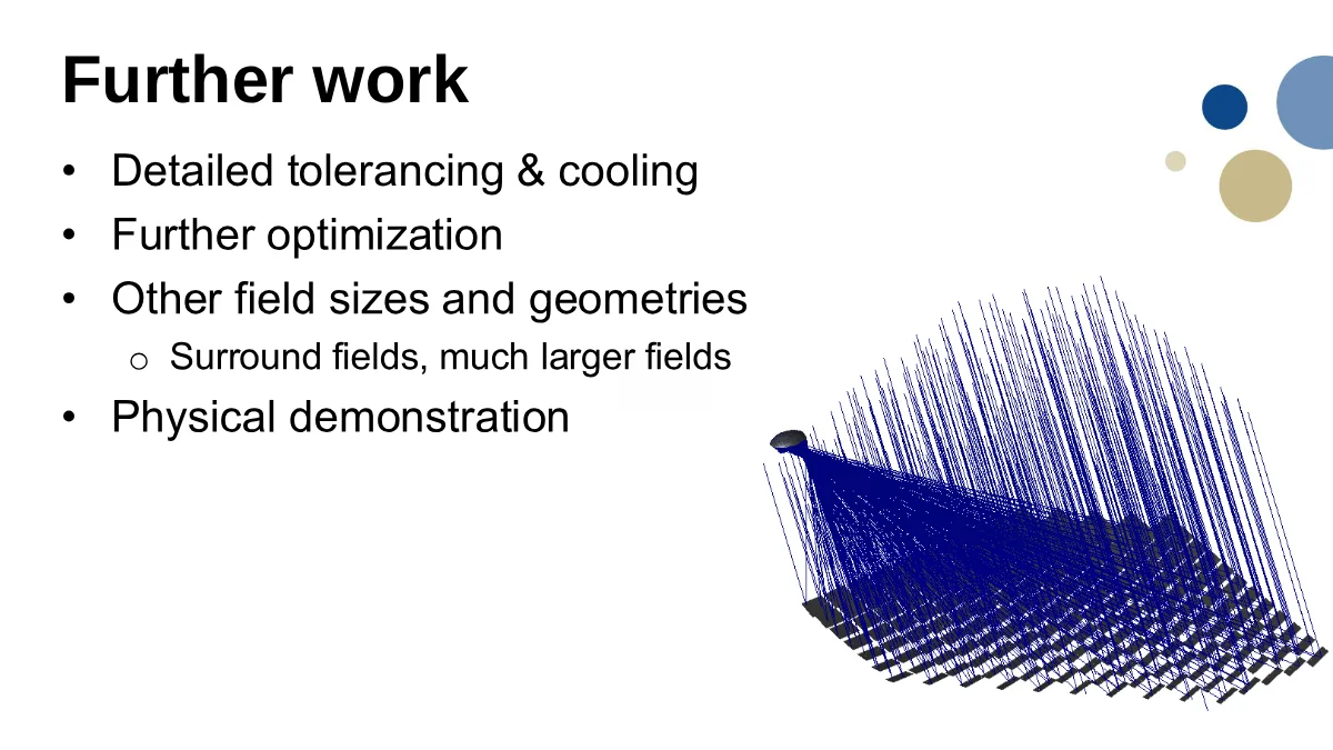
There is a lot more work to do here. The tolerancing and cooling need to be studied properly, and the optimization itself can be improved.
Other field sizes and geometries are also important. This test case is a small compact field, but in principle the same idea should work for surround fields and much larger fields as well.
And of course, the next step after simulation is a physical demonstration. Perhaps at the IMDEA Energy solar field?