Angular control for improved spectral filtering in thermophotovoltaics
This post is a lightly edited version of a talk I gave at the Nonimaging Optics Conference in August 2026 about an interesting concept for spectral filtering. The complete recording will be published in September as part of the conference proceedings.
The application focus of this talk was thermophotovoltaics, a fascinating type of solid-state heat engine where we take thermal radiation from a glowing-hot emitter surface and convert it to electricity:
A central part of thermophotovoltaics is the coupling of thermal radiation from the hot emitter surface to the PV cell, and this is where nonimaging optics comes in:
Before we answer this question, we need to briefly recap how thermophotovoltaics actually work.
I will explain the principle of thermophotovoltaics by example. Let’s look at a surface at a hot temperature, say 1500 °C. At this temperature, the surface emits strong thermal radiation. The spectrum of its thermal radiation is given by Planck’s law and is shown by the red plot below. Some of you might be more accustomed to spectrum plots in terms of wavelength, so I included a control to switch between the two. In TPV work, it is often useful to represent the spectrum in terms of energy per photon, measured in electron volts (eV):
The green plot in the slide above shows the approximate efficiency of a 0.74 eV InGaAs TPV cell, a popular type of cell for high-efficiency thermophotovoltaics.
The exact efficiency depends on multiple factors that require more detailed modelling, but the model above considers the following:
-
For photons with energies below the bandgap energy of the PV cell, the cell has zero efficiency. The photons do not have enough energy to excite electrons across the bandgap, so they pass through the material.
-
For photons at the bandgap energy, the photons are absorbed and efficiently create electron-hole pairs in the cell. The resulting cell efficiency depends on many factors, including how strongly the cell is illuminated and how much current is drawn from it, but 50% is a reasonable back-of-the-envelope value for a fairly good cell.
-
As photon energy increases, photons are still absorbed and create electron-hole pairs, but the extra photon energy beyond the bandgap turns into heat, so cell efficiency gradually falls at higher photon energies.
If we combine the two plots above and calculate a spectrum-weighted conversion efficiency, we get the following:
The result is only approximately 10% efficiency. This is certainly not a good heat engine yet, but we have an important trick up our sleeves to make it much better:
We have the luxury that our hot surface is nearby, so it is possible to take any photons that are not efficiently turned into electricity and send them back to the hot surface, where they will be reabsorbed. In this way, we can reduce thermal losses in the system and increase its efficiency.
If we can efficiently send the low-energy photons back to the emitter, we can significantly increase the efficiency of thermophotovoltaics. Efficient photon recycling is key to all TPV efficiency records, such as those by Swanson, Omair, LaPotin, and Fan.
Photon recycling can be implemented in a few different ways:
-
We can use selective emitters that emit preferentially in the wavelength band where the PV cell is most efficient. This approach has received significant attention, but it is challenging because the selective-emitter material must withstand emitter temperatures of approximately 1000 °C to 2000 °C.
-
We can use dielectric filters in front of our mirrors. This approach has also received significant attention, but it is challenging to design filters that work well enough over the full range of angles and wavelengths to which the filter will be exposed.
-
The third, and currently overwhelmingly most common, approach is to make the back side of the photovoltaic cell reflective and take advantage of the fact that the PV cell is mostly transparent to below-bandgap photons. This works, but all recycled radiation then passes through the PV cell twice. The cell must be engineered to be very transparent to all sub-bandgap photons, and any optical loss directly heats the PV cell, which we want to keep as cold as possible for the best performance. This approach also allows us to filter only sub-bandgap photons, not the high-energy above-bandgap photons that the PV cell also converts inefficiently.
I want to look a little closer at dielectric filters. The principle is quite elegant: a filter is a stack of materials with different refractive indices, arranged so that light reflected from the interfaces constructively interferes in the wavelength ranges we want to reflect and destructively interferes in the wavelength ranges we want to transmit.
Dielectric filters


Multilayer thin-film structures transmit only specific wavelengths
These filters work quite well and let us precisely control the spectrum of transmitted and reflected light, as well as absorbed light to a certain extent. Thorlabs and other optics suppliers stock a large range of such filters, so we can find a bandpass filter in approximately the wavelength region we need:
Let’s buy a dielectric filter
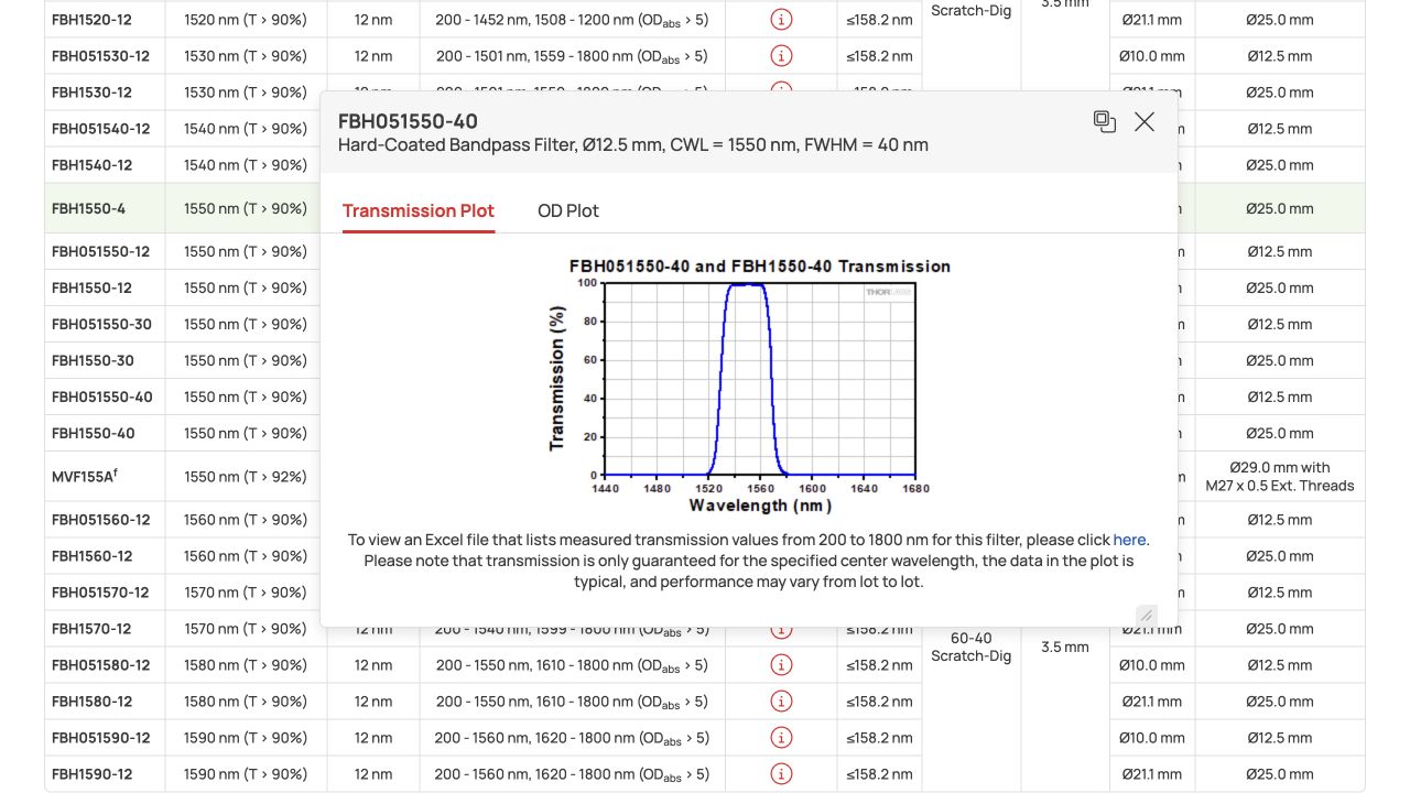
As you can see, this filter looks very good. It transmits almost all the light in a narrow band and almost nothing at other wavelengths. We would probably want a wider band to transmit a significant power density, and we need the filter to have very low absorptivity so that blocked light is reflected rather than absorbed. Still, it is clearly possible to design filters with the required spectral performance.
So why is it not standard practice in thermophotovoltaics to buy such a filter and put it in front of the photovoltaic cell? We get the answer if we look further down the Thorlabs page:
Let’s buy a dielectric filter
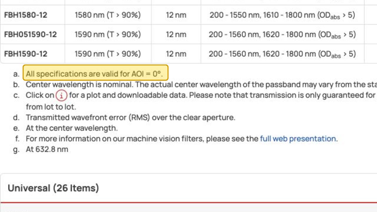
The specified filter performance is for light at an angle of incidence of 0°. Dielectric filters are sensitive to the angle of incidence. It is easy to design a filter that performs very well at one angle, but at other angles the light has a different path length through the layers. This shifts the wavelengths and disrupts the carefully tuned constructive and destructive interference.
This is a problem because thermal radiation is both broadband and broad-angle: it spans the full range from 0° to 90°.
We can plot the angular performance of a bandpass filter designed for an angle of incidence of 0°:
The filter above works very well at an angle of incidence of 0°, transmitting a specific band and reflecting everything else across an extremely wide spectrum. However, as soon as we look at higher angles, this performance degrades. The wavelengths shift and the carefully tuned behavior stops working.
This is where the field of nonimaging optics comes in:
We know how to reduce angular extent
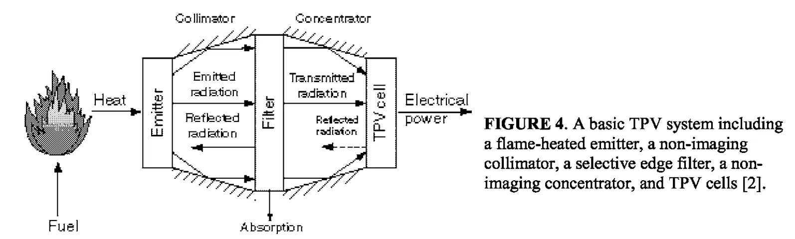
Nonimaging optics is all about controlling the spatial and angular extent of light, and we know how to tune these properties. In the early 2000s, Lindberg wrote a PhD thesis about using nonimaging optics to improve filtering in thermophotovoltaics. He proposed using optics to first reduce the angular extent of the light by collimating it, then filter the light over its now narrower angular range, and finally focus it onto a PV cell.
Lindberg’s approach is quite interesting, but it introduces multiple optical components before the cell: a collimator, a filter, and a concentrator. Their losses add up, especially those from the collimator and filter. Efficient thermophotovoltaics depends on extremely low-loss recycling of low-energy photons, ideally with losses of less than a couple of percent. When the low-energy photons must reflect from a collimator one or two times in addition to reflecting from the filter, the losses quickly exceed those from using the cell itself as the filter.
We therefore want a way to reduce the angular extent of the light without the losses associated with reflecting it from a collimator. This brings us to an interesting geometry that also appears in my presentation on photon recycling for solar thermal receivers from the same conference:
As explained in the other post, a semi-ellipse perfectly recycles light from a disc-shaped emitter back onto the disc-shaped emitter. It also has another interesting property that can be useful here: it needs to reflect light over only a reduced angular extent.
No matter where the light hits the ellipse, it always arrives within a cone around the local surface normal, with an angular extent of less than ±90°. The exact angular extent depends on the size of the ellipse:
If we coat the inside of this ellipse with a dielectric filter, we therefore make significant progress on the issues with dielectric filters for thermophotovoltaics:
-
We have reduced the angular extent of the light, so we no longer need to design the filters for performance across the full hemisphere.
-
One surface performs both filtering and recycling, so there are no extra reflection losses associated with reducing the angular extent.
We want to explore how well such a geometry will perform, so we need to design and simulate some dielectric filters. This means that we first need to take a detour and think more carefully about how we want these filters to behave.
We will use the breakdown of thermophotovoltaic efficiency proposed by Burger et al., who separate it into spectral efficiency (SE), internal quantum efficiency (IQE), voltage factor (VF), and fill factor (FF).
Voltage factor and fill factor depend on the quality of the PV cell and on how strongly it is irradiated, so we can ignore them when optimizing the filter. IQE and filter performance are somewhat intertwined, but as a simplifying assumption we can take IQE to be close to unity. We then get a useful single number describing the filter performance: spectral efficiency, SE. For a dielectric filter and unity IQE, we can estimate this spectral efficiency as follows:
Spectral efficiency is a fraction of useful power divided by used power. The numerator is the flux of above-bandgap photons transmitted to the cell, weighted by the bandgap energy, which is the useful fraction of those photons’ energy. The denominator is the total flux that is not reflected back onto the emitting surface, meaning the total radiative heat loss from the emitter.
We can plot this spectral efficiency in a form very similar to the previous plot of thermophotovoltaic efficiency:
The photons just above the bandgap contribute 100% to the spectral efficiency. Photons at lower energies contribute nothing, while at higher energies an increasing amount is lost because the mismatch between the photon energy and the bandgap energy of the photovoltaic material grows.
Now we have a merit function, also known as an objective function, and we can optimize a filter directly for it. Let’s try to design some filters using this merit function:
As a first example, we ignore the effect of angular extent and design our filter for an angle of incidence of 0°. It is clear that it is possible to design a very good dielectric filter:
When evaluated at an angle of incidence of 0°, the optimized filter above gives a spectral efficiency of 82%. For comparison, typical back-mirrored TPV cells have spectral efficiencies of 50% to 70%.
However, if we evaluate the filter over the full hemisphere, which is what it will experience in conventional use in a thermophotovoltaic system, the spectral efficiency drops significantly, and we see both less available power and greater losses of low-energy photons.
A first step, before we start restricting the angles, could be to optimize directly for spectral efficiency for a filter that receives light over the full hemisphere:
Optimizing for performance across the full hemisphere did improve our performance quite a lot and might be valuable in itself. Still, we see that we are no longer able to get the sharp filter cutoff exactly at the bandgap.
So let’s now assume that we use our elliptical geometry to restrict the angles of incidence that the filter will see, for example, to a cone of ±45°:
By restricting the angles of incidence to a certain range and optimizing for this whole range, we have been able to recover almost all the filter performance that we saw at an angle of incidence of 0°. It is therefore clear that reducing the angle of incidence on our filter is valuable.
The question now is how we would implement this in a real device. This is still a somewhat open question, but below is one possible implementation:
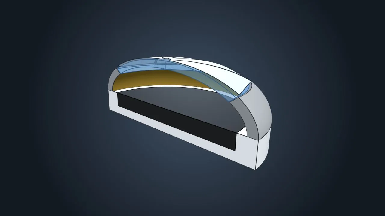
The model above shows how a black emitting surface can be covered by an oblate spheroid, the 3D version of the semi-ellipse we are discussing. The periphery of the cover is highly curved, so it might be difficult to deposit a high-quality dielectric filter there. However, the amount of light is also relatively low there, so we can use a thick gold coating to simply reflect most of that radiation. For the central part, we use a fused silica window whose inner surface is coated with the dielectric filter. This way, only the wavelengths we want are transmitted through the window, and the rest are redirected back to the emitter.
Finally, we can place PV cells outside this window to efficiently convert the transmitted radiation to electricity.
The geometry shown above is one way to implement a proof of concept, but a real application might be coupled with thermal energy storage. It could look something like the following, where the emitting surface is replaced by a cavity opening in a high-temperature thermal energy store:
This concept is an interesting way to potentially improve the spectral filtering performance of a dielectric filter for TPV applications. There are still a couple of challenges to overcome, most importantly:
-
The reduced angular extent of the thermal radiation is equivalent to reduced power density. For ±45°, the power density is 50% of the power density at ±90°. With the high cost of TPV cells, this might need to be considered part of the trade-off, and it might be necessary to look at ways to reconcentrate the light onto a cell after filtering.
-
Applying dielectric filters on highly curved surfaces is somewhat tricky and requires a lot of tuning to get uniform thickness across the different parts of the surface.
The concept is not yet a slam dunk, but I think it definitely is a topic that deserves further research and more detailed modelling.