Photon-recycling cavities for high-temperature solar receivers
In August 2026, I gave a presentation at the Nonimaging Optics Conference about an interesting type of design for high-temperature solar collectors.
The talk recording will be published as part of the conference proceedings, but here is a lightly edited overview of the slides and the topic of the presentation.
A major historical focus of nonimaging optics has been on ways to efficiently and strongly concentrate sunlight for solar thermal applications:
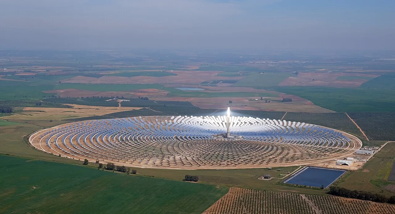
Solar concentration
Photo:kallerna / Wikimedia Commons·CC BY-SA 4.0· cropped

Solar concentration is really cool, but as scientists in this field it is easy to get a bit carried away by the ability to reach extremely high concentration levels. I think it can be helpful to take a step back and think about why we want to concentrate the light in the first place for solar thermal applications.
We concentrate sunlight to reduce thermal losses to the environment and increase the efficiency of the heat we can extract from the system. These thermal losses come in different forms, but at high temperatures they show up overwhelmingly as thermal radiation, due to the T⁴ term in the Stefan–Boltzmann law.
Let’s visualize this by looking at the flow of heat in a receiver under a specific receiver temperature and amount of incoming sunlight. At some receiver size, most of the heat is emitted back out as thermal radiation. If we reduce the size of the receiver, we can reduce the emitted thermal radiation and increase the useful heat we can extract from it:
We can use this relationship between incoming sunlight and emitted thermal radiation to plot the efficiency of a receiver at different temperature levels. It is clear that if we want high temperatures, such as 1500 °C to 2000 °C, we need very high levels of concentration:
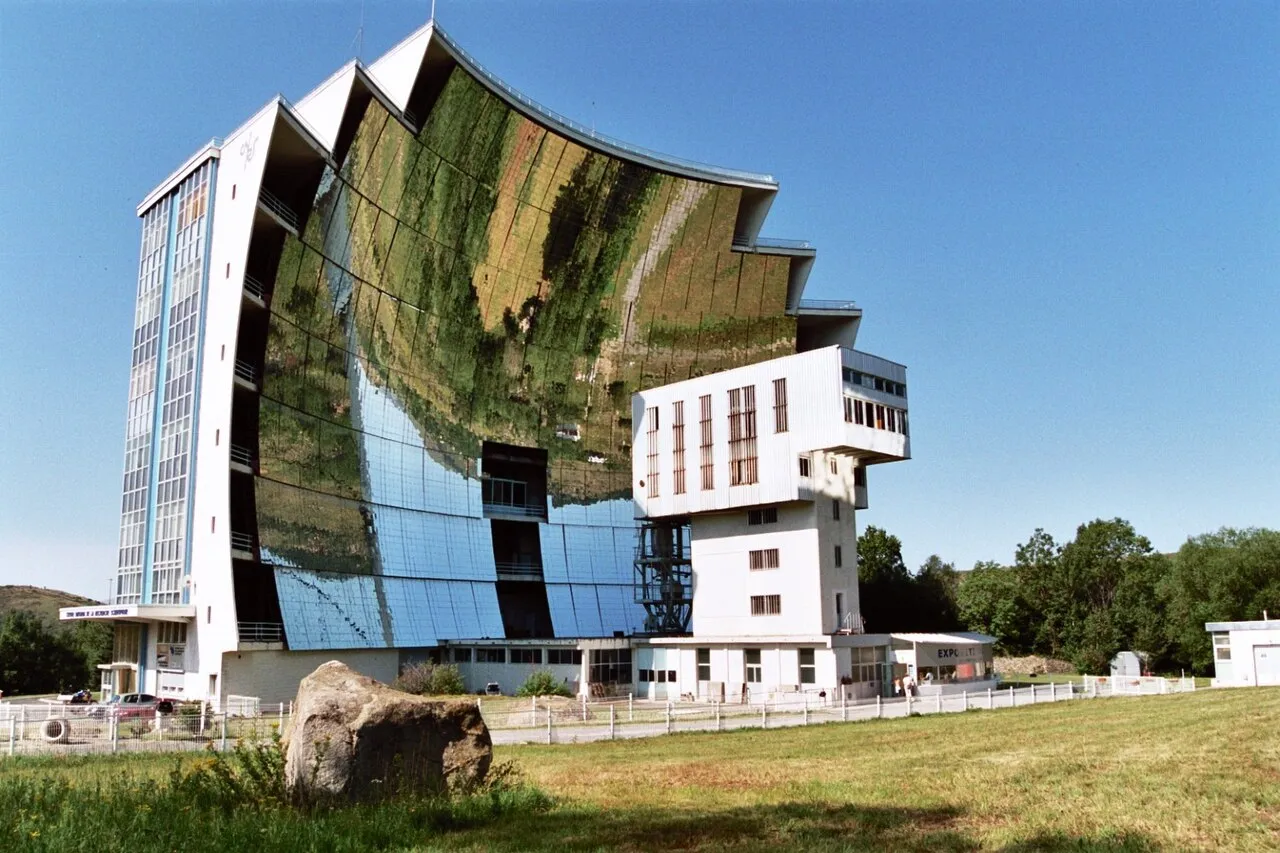
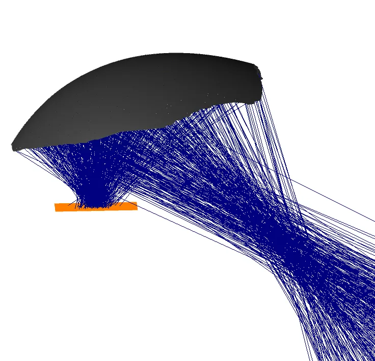
Some solar thermal applications require these very high concentration ratios. They are typically achieved using solar furnaces, parabolic dish concentrators, or possibly secondary concentrators like the one in my 2024 SolarPACES talk:
Getting to higher concentration

However, at this point I think it is important to take a step back and remind ourselves why we concentrate sunlight:
Our goal is not inherently to concentrate sunlight. Our goal is to use the heat from the sun while reducing the amount of heat lost to the environment. Concentration is the typical way we reduce the thermal radiation lost to the environment, but it is not the only way.
There are other approaches, such as spectral selectivity (designing materials with high absorptivity over the solar spectrum but low emissivity in the longer-wavelength thermal-radiation spectrum), angular selectivity (avoiding thermal emission in directions other than toward the sun), or photon recycling (reflecting thermal photons back toward the receiver).
My goal here is to take a deeper look at photon recycling for solar thermal applications.
Photon recycling is a way to reduce the radiative heat loss from a surface emitting thermal radiation. Instead of reducing the size of the surface, we redirect a large fraction of the emitted photons back toward it:
Photon recycling is not new. It has been researched fairly heavily for increasing the efficiency of photovoltaics, increasing the brightness of incandescent sources, and especially improving the efficiency of thermophotovoltaics.
The concept has also been proposed for solar thermal applications, but I am aware of only a couple of references: Jeffrey Gordon’s work presented at the 2004 Nonimaging Optics Conference and Weinstein et al.’s paper, “Optical cavity for improved performance of solar receivers in solar-thermal systems”.
I think the idea deserves more focus and research.
Previous applications
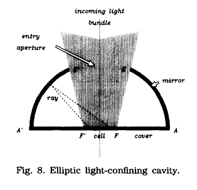
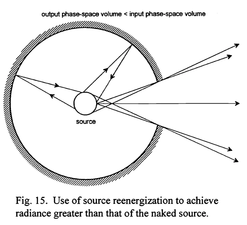
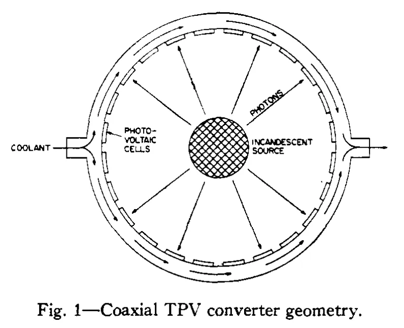
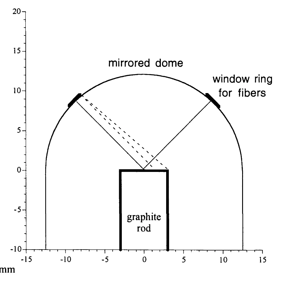
If we look at the examples from the references above, they have very similar geometries: either concentric spheres or semi-ellipses over flat discs. There is a reason for this: these are ideal geometries for photon recycling. I think the semi-ellipse is especially interesting here, so let’s look at it a bit more closely:
When we look at a flat receiver from the side, it becomes a straight line segment. If we take the two endpoints of this line and use them as focal points to construct an ellipse, any ray of light from one endpoint is, by definition, reflected to the opposite endpoint by the ellipse.
If we now consider any ray from any point between those endpoints, the ray will reflect back to some other point between the endpoints:
The fascinating thing about this relationship is that it also holds in three dimensions if we revolve our geometry about the vertical axis to create the geometry known as an oblate spheroid:
This is quite surprising! If we have a nonimaging optical design that is ideal in two dimensions, it does not immediately follow that the three-dimensional equivalent will be ideal. For instance, the compound parabolic concentrator is ideal in 2D but not in 3D.
One way to understand this geometry is to consider the flow lines from a flat emitter. These flow lines are hyperbolas with the endpoints of the emitter as focal points. If we create a mirror that is everywhere normal to these flow lines, we reflect the optical flow field without disturbing it, meaning that we send the light back exactly where it came from. The geometry that is everywhere normal to hyperbolas with a pair of focal points is an ellipse with the same two focal points. The ellipse is therefore the geometry that perfectly returns the light to the receiver.
The flow-line argument also holds in 3D and helps explain why this geometry turns out to be ideal both in 2D and in 3D.
If we want to use this geometry for solar thermal applications, we need a way to let sunlight enter the system. The simplest approach is to cut a hole in the ellipse where we want the sunlight to enter:
The flow-line perspective is again useful, as it tells us exactly how much radiation from our receiver can exit through the opening:
In the example shown above, the ellipse is cut along the flow lines emanating from the central half of the receiver (the red part). In three dimensions, this central part is one half by one half, or one quarter of the area. Since the net flux across a flow line is zero, the opening in our ellipse lets out one quarter of the thermal radiation from our source.
Another way to look at this is that this size of hole in the ellipse provides a 4× “equivalent concentration”: the reduction in thermal radiation is equivalent to what we would get from reducing the receiver size by a factor of 4. This factor comes from which hyperbola we use to cut the opening in the ellipse, and is independent of the actual ellipse size.
Depending on the size of ellipse we choose, this approach gives rise to a range of receivers with the same equivalent concentration:
-
A large ellipse provides angular restriction: light at wide angles is recycled, while light at narrower angles is allowed to escape.
-
A small ellipse provides spatial restriction: light from the periphery of the receiver is recycled, while light from the center is allowed to escape.
-
A medium-sized ellipse provides a mix of the two and has some interesting properties that I believe are worth exploring.
If we take one of these medium-sized ellipses and look at the directions in which light is allowed to escape, this tells us how to design an ideal solar concentrator to couple into this receiver:
An ideal concentrator would have to send sunlight in exactly the directions in which these rays are allowed to escape. Designing a concentrator for ideal coupling is not completely trivial (I am happy to discuss if anyone has thoughts), but a simple approximate solution would be to use an existing concentrator with a lower-than-unity numerical aperture.
The potential benefit of photon recycling compared with pure optical concentration is that we can reduce the thermal load on our receiver.
As an example, let’s consider a receiver at 1500 °C. This receiver emits thermal radiation at approximately 0.5 MW/m². To achieve good efficiency, the standard approach is to overwhelm the receiver with sunlight much stronger than this so that thermal radiation becomes insignificant by comparison.
The problem is that the resulting extremely intense sunlight is very damaging to anything in its path. If we aim for 80% efficiency, for example, this means something like 2.8 MW/m², which will rapidly heat anything in its path to almost 1000 °C above our target temperature. We therefore need to be extremely careful about the receiver design, ensuring that everything is very well cooled and that sunlight never goes where it is not supposed to.
If we instead use photon recycling to improve efficiency without overwhelming our receiver with extremely intense sunlight, we can achieve the same target efficiency with much lower flux density. Any small uncooled part of the receiver that ends up in the path of the concentrated sunlight will then have an equilibrium temperature close to our target temperature rather than far above it.
An additional potential benefit is that our photon-recycling mirror sees only the less intense thermal radiation instead of needing to handle the extremely intense concentrated sunlight.
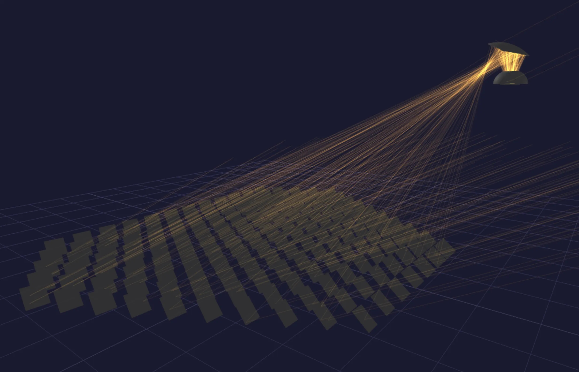
Let’s look at what this might mean for a real heliostat field. As a starting point, we will use the IMDEA Energy very-high-concentration solar tower in Madrid. This is a small, dense field that already achieves relatively high flux densities and, with a small beam-down secondary like the one we proposed last year, achieves very high concentration.
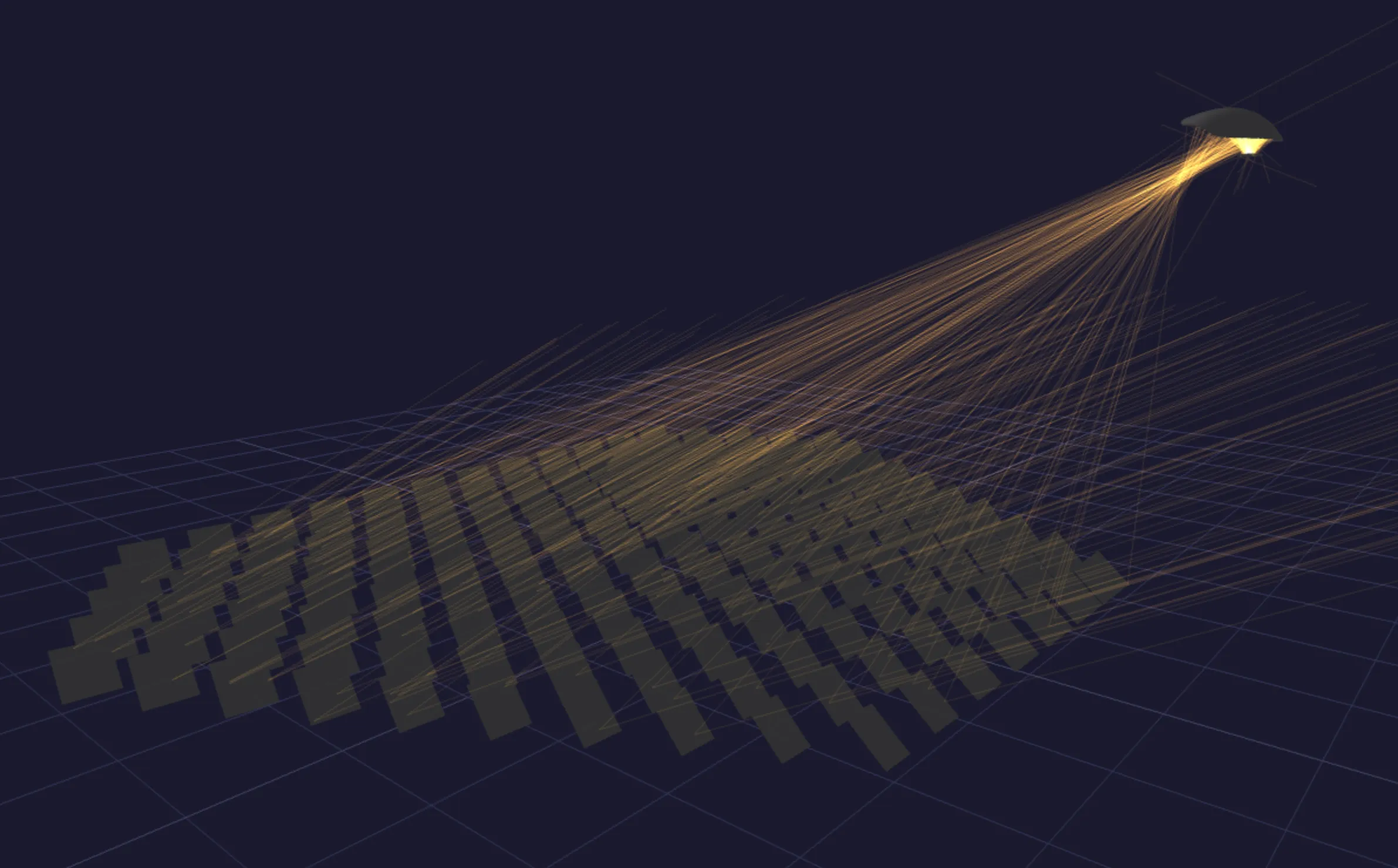
Heliostat concept
hakonjohnsen.no/posts/2024-aplanatic-solarpaces/If we reoptimize that secondary concentrator for lower numerical aperture and surround the receiver with a photon-recycling cavity, we get the following:
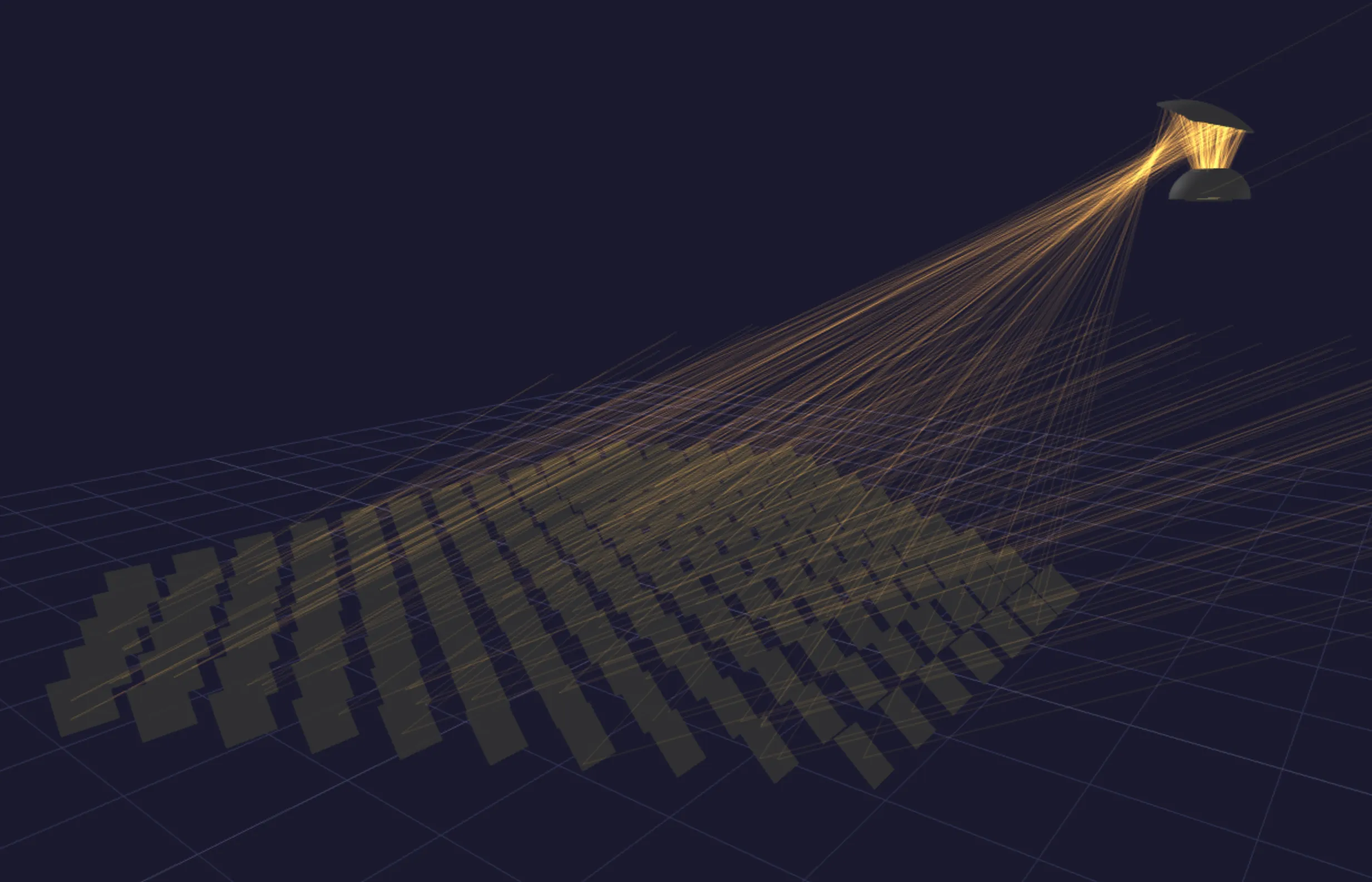
Heliostat with secondary + photon recycling
The reduced numerical aperture of the concentrator means that it has a wider and less intense focal spot. We can compare the predicted flux density of our previously proposed high-NA concentrator and the new low-NA concentrator here:
Comparison
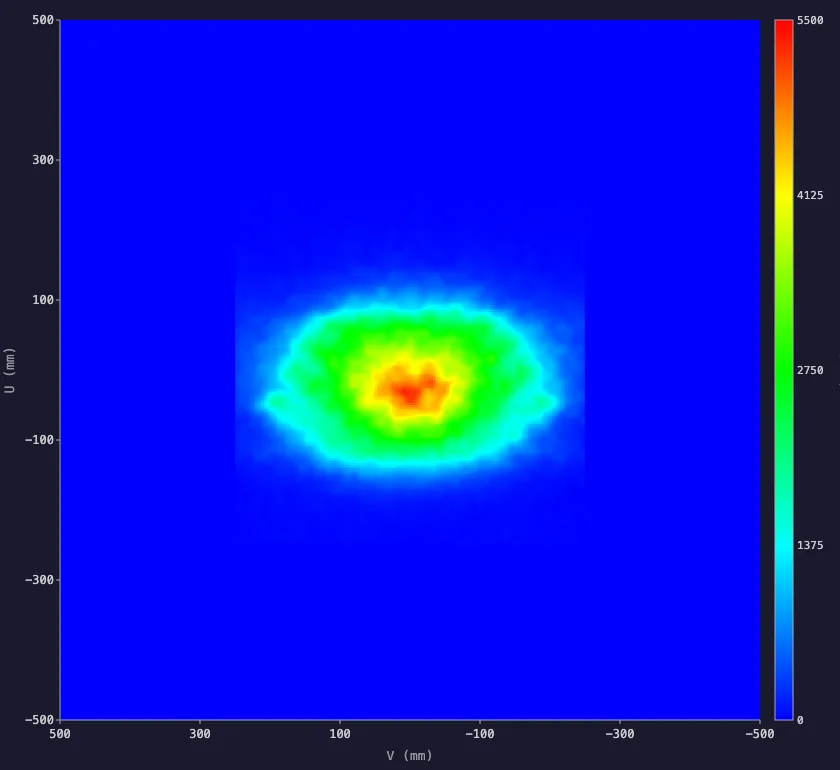
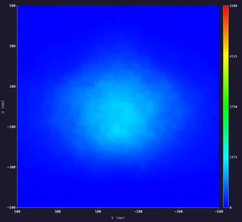
However, the photon-recycling cavity around the receiver in this example has an equivalent concentration of 4.1. If we boost the simulated flux density by this amount to obtain what we might describe as an “equivalent irradiance,” we get the following:
Equivalent irradiance
.BU6MGJ3C_Z2yATD.webp)
In essence, we have reduced the flux density and never generated the extremely intense solar flux, but we have still reduced the thermal losses by an amount similar to our original high-NA secondary concentrator.
These results are quite preliminary, and more detailed modelling and optimization are certainly warranted. This example was not optimized directly for performance with photon recycling beyond reducing its numerical aperture, so there is probably more performance to extract if everything is optimized together.
I think photon recycling is a very interesting concept in the context of solar thermal applications, and that the semi-elliptical mirror (and its 3D version, the oblate spheroid) is a fascinating geometry whose thermodynamically ideal performance deserves further exploration.